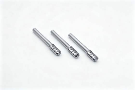
When selecting tungsten carbide rotary burrs, most buyers focus on carbide grade, hardness, or shank size—but often overlook one of the most important performance factors: tooth geometry.
The tooth design (also called flute or cutting pattern) directly determines cutting speed, chip removal efficiency, surface finish, heat generation, and tool lifespan.
If you are a tool distributor, industrial buyer, or factory purchasing manager, understanding tooth geometry will help you choose the right carbide burr for each application—and avoid unnecessary tooling costs.
What Is Tooth Geometry in Carbide Rotary Burrs?
Tooth geometry refers to the shape, size, and layout of cutting edges on the carbide burr head. These cutting teeth remove material by high-speed rotary grinding, and the tooth structure controls:
- How aggressively material is removed
- How smoothly the burr cuts
- How chips are discharged
- How long the burr lasts
A well-designed tooth pattern improves cutting efficiency by 30–50% and reduces tool wear significantly.
Common Tooth Types of Carbide Burrs
Tooth Type
Appearance
Best For
Features
Single Cut(SC)
Spiral teeth in one direction
Steel, cast iron
Fast stock removal
Double Cut(DC)
Cross-cut teeth
Stainless steel, hardened steel
Smoother finish, stable cutting
Aluminum Cut(AL)
Large single flute
Aluminum, brass, plastics
Anti-clogging
Single Cut vs Double Cut vs Aluminum Cut – Performance Comparison
Performance Factor
Single Cut
Double Cut
Aluminum Cut
Cutting Speed
★★★★
★★★
★★★★★
Surface Finish
★★
★★★★
★★★
Chip Control
★
★★★★
★★★★★
Vibration Stability
★★
★★★★
★★★
Best For
Steel, cast iron
SS, alloy steel
Aluminum, copper
*If you’re selling to metal workshops or distributors, always include all 3 tooth types in your catalog—they cover 90% of market needs.
How Tooth Geometry Affects Cutting Performance
1. Chip Removal Efficiency: Large flute designs remove chips faster (best for aluminum), while cross-cut teeth reduce chip size (best for stainless steel).
2. Cutting Speed: Aggressive flute geometry increases removal rate but also requires higher RPM and stable tools.
Recommended Operating Speeds
Burr Head Diameter(rmp/min)
3mm(1/8")
6mm(1/4")
10mm(3/8")
12mm(1/2")
16mm(5/8")
Maximum Operating Speed
90000
65000
55000
35000
25000
Aluminum, Plastic
Usable Range
60000-80000
15000-60000
10000-50000
7000-30000
6000-20000
Recommended Starting Speed
65000
40000
25000
20000
15000
Copper, Cast Iron
Usable Range
45000-80000
22500-60000
15000-40000
11000-30000
9000-20000
Recommended Starting Speed
65000
45000
30000
25000
20000
Mild Steel
Usable Range
60000-80000
450000-60000
30000-40000
22500-30000
18000-20000
Recommended Starting Speed
80000
50000
30000
25000
20000
Hear-treated Steel,etc
Usable Range
60000-80000
30000-45000
19000-30000
15000-22500
12000-18000
Recommended Starting Speed
80000
40000
25000
20000
15000
3. Heat Generation: Wrong tooth type = excessive heat = tool wear + burns on workpiece.
4. Vibration & Stability: Double cut burrs reduce vibration and improve control—ideal for manual die grinder operations.
5. Tool Life: Optimized tooth geometry reduces friction and loading—extends burr life by 25–40%.
Choosing the Right Tooth Geometry for Different Materials
Material
Recommended Tooth Type
Reasons for recommendation
Carbon steel
Single Cut
Aggressive cutting
Stainless steel
Double Cut
Prevents work hardening
Hardened steel
Double Cut
Stable cutting
Aluminum
Aluminum Cut
Prevents loading
Titanium
Double Cut
Stability under heat
Brass/Copper
Aluminum Cut
Clean cutting
FAQ – Buyers Also Ask
Q1: Which carbide burr tooth type lasts longest?
Double cut burrs generally provide the best balance between speed and tool life.
Q2: Can I request special tooth geometry?
Yes—OEM customization of tooth design is available for volume orders.
Q3: What tooth type is best for stainless steel?
Double cut burrs—reduce hardening, smoother control.
Conclusion
Tooth geometry directly controls cutting speed, chip removal, surface finish, heat, and tool life. Choosing the right tooth design means higher performance and lower tooling cost.
We manufacture tungsten carbide rotary burrs for global tool distributors and industrial users. We have the following main advantages:
- Ultra-fine grain carbide WC
- CNC 5-axis precision grinding
- High-strength silver brazing
- Standard & customized tooth geometry
- Bulk factory price+fast delivery
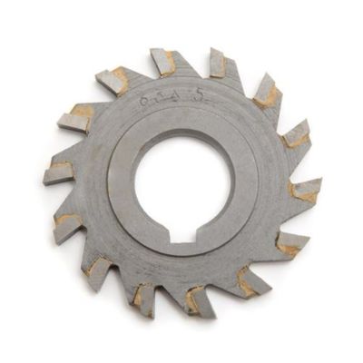
The brazing technology and brazing material selection directly determine the quality level of carbide burr.
The welding technology of carbide rotary burrs is one of the key factors that affect their quality. The choice of welding materials and welding processes directly determines the quality level of the carbide rotary burrs.
Selection of welding materials: Carbide rotary burrs use a core-sandwich silver brazing material, which has silver at both ends and a copper alloy core layer in between. The welding temperature for this material is around 800°C, which is much lower compared to the 1100°C welding temperature required for copper brazing materials. This significantly limits the damage to the carbide properties, reduces welding stress, prevents microcracks in the carbide, and provides better welding strength.
Selection of welding methods: There are currently two main welding methods in the market: flat-bottom silver brazing and tail-hole copper brazing. Flat-bottom silver brazing has a simpler structure, lower welding stress, and lower required welding temperature, which better preserves the performance of the alloy and steel handle. On the other hand, tail-hole copper brazing can save some carbide material and is cheaper, but the higher welding temperature may cause damage to the carbide properties.
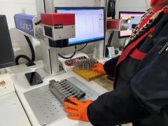
Welding equipment and process: Using automatic welding machines is a crucial part of the process. In the automatic welding process, the carbide tip and steel handle can automatically align for brazing without manual intervention, greatly ensuring the stability of the welding quality and excellent coaxiality between the steel handle and carbide tip after welding.
Why is Flat-Bottom Silver Brazing Technology Critical for Carbide Burrs?
The most common failure in rotary files is "head-breakage" at the welding point. At BABOS, we eliminate this risk by utilizing advanced Flat-bottom Silver Brazing Technology.
Unlike standard welding methods, our process involves:
Maximized Surface Contact: The flat-bottom design ensures 100% contact between the carbide head and the steel shank, creating a bond that is significantly stronger than traditional pointed or irregular joints.
Premium Silver Solder: We use high-grade silver brazing filler, which offers superior thermal conductivity and shock resistance, preventing the tool from loosening due to heat expansion during heavy-duty grinding.
Zero-Breakage Guarantee: This precision welding technique ensures that our tools can withstand high RPMs and extreme lateral pressure, providing industrial distributors and end-users with a reliable, "zero-risk" performance.
As a company with over ten years of experience in carbide material research and development, Chengdu BABOS Cutting Tools has a deep understanding of carbide material performance. During the welding process of rotary burrs, we use fully automated flat-bottom silver brazing technology, which greatly protects the alloy's performance and ensures excellent coaxiality between the steel handle and the carbide tip.
Writen by: Villa Wang
LinkedIn: https://www.linkedin.com/in/villa-wang-938973339
Virgin vs. Recycled: Why Is Your Carbide Burr’s Lifespan So Short?
In the world of industrial metalworking, the price of Carbide Burrs can vary significantly between suppliers. Many procurement managers are initially attracted by low prices, only to discover in production that the tools wear out prematurely, break easily, or leave a poor surface finish.
The root cause of this performance gap lies in one critical factor: The quality of the raw material.
1. What is 100% Virgin Micro-grain Tungsten Carbide?
Virgin Material refers to tungsten carbide powder extracted directly from tungsten ore that has never been used or processed before. Its grain structure is extremely fine—often at the micron level—and perfectly uniform.
In contrast, Recycled Material (Scrap Carbide) is made by grinding down old, used tools and re-pressing them. While it is still technically "carbide," its physical properties have been fundamentally compromised.
2. In-Depth Comparison: Virgin vs. Recycled
2.1Hardness & Wear Resistance
Virgin Material: Offers superior hardness and "red hardness" (the ability to maintain a sharp edge at high temperatures). At high speeds (20,000 – 50,000 RPM), the cutting edges remain sharp for extended periods.
Recycled Material: Due to impurities and mixed grades from various scrap sources, the hardness is inconsistent. When machining tough metals like stainless steel, the cutting edges dull almost immediately.
2.2 Toughness & Impact Strength
This is the key to preventing "head breakage."
Virgin Material: The uniform micro-grain structure provides excellent transverse rupture strength (TRS). When combined with flat-bottom silver brazing technology, it effectively absorbs high-frequency vibrations and impact.
Recycled Material: Contains microscopic pores or internal micro-cracks. Under lateral pressure, these tools are prone to chipping or snapping off entirely at the weld point.
2.3 Precision & Consistency
Virgin Material: During the CNC grinding process, the stable material allows for high-precision flute geometry. This ensures smooth chip evacuation and a superior surface finish on the workpiece.
Recycled Material: Often leads to irregular wear during manufacturing, resulting in inconsistent performance from one batch to the next.
3. Why Cheap Carbide Burrs Actually Cost You More
Saving 20%–30% on the initial purchase of recycled carbide burrs may seem like a bargain, but a Return on Investment (ROI) analysis tells a different story:
Frequent Tool Changes: Tools made from virgin material typically last 3 to 5 times longer than recycled ones.
Increased Downtime: Every time a tool fails or dulls, your production line stops, significantly increasing labor costs.
Workpiece Damage: Low-quality tools generate excessive heat, which can warp or damage expensive workpieces.
4. Conclusion: How to Identify High-Quality Burrs
As a professional manufacturer, BABOS insists on using 100% virgin micro-grain raw materials. We recommend checking these three points when sourcing:
The "Weight" Test: Due to higher density and purity, virgin carbide feels significantly heavier than recycled alternatives of the same size.
The Cutting Sound: High-quality tools produce a crisp, consistent sound with minimal vibration during operation.
Supplier Certification: Always ask your manufacturer for a raw material certificate.
There are currently two main welding methods in the market: flat-bottom tail-hole copper brazing and silver brazing. Let's briefly describe the advantages and disadvantages of these two welding methods, which may help customers make a better choice.
Tail Hole Copper Welding
• Advantages:Lower cost,larger contact area for welding,theoretically higher strength.
• Disadvantages:Complex welding process, high welding temperature(about 1100°C), significant impact on tool structure, potential for performance instability. High temperature can cause cracks in the hard alloy, concentrated welding stress, and greater quality fluctuation.
Flat Bottom Silver Welding
•Advantages: Simple welding structure, low welding stress, lower required welding temperature(about 800°C), better preservation of the performance of both the alloy “head” and the steel shank. Higher welding strength, more stable quality, better durability. The core design effectively reduces welding stress and eliminates microcracks.
• Disadvantages:Higher cost.
If high performance,high-speed operation,and long service life of the hard alloy rotary file are required,flat bottom silver welding is recommended.Although it is slightly more expensive,it provides better stability and reliability.If cost is a concern and the usage scenario does not have high requirements for tool performance,tail hole copper welding is also an option to consider.
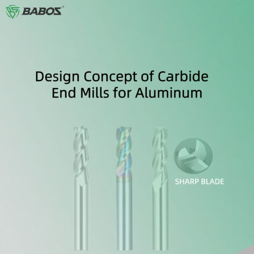
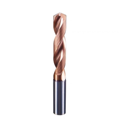
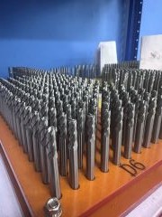
Introduction
When designing carbide end mills for aluminum, it is essential to comprehensively consider material selection, tool geometry, coating technology, and machining parameters. These factors ensure efficient and stable machining of aluminum alloys while extending tool life.
1. Material Selection
1.1 Carbide Substrate: YG-type carbide (e.g., YG6, YG8) is preferred due to its low chemical affinity with aluminum alloys, which helps reduce built-up edge (BUE) formation.
1.2 High-Silicon Aluminum Alloys (8%–12% Si): Diamond-coated tools or uncoated ultrafine-grain carbide are recommended to prevent silicon-induced tool corrosion.
1.3 High-Gloss Machining: High-rigidity tungsten carbide end mills with precision edge polishing are suggested to achieve a mirror-like surface finish.
2. Tool Geometry Design
2.1 Number of Flutes: A 3-flute design is commonly used to balance cutting efficiency and chip evacuation. For rough machining of aerospace aluminum alloys, a 5-flute end mill (e.g., Kennametal KOR5) can be chosen to increase feed rate.
2.2 Helix Angle: A large helix angle of 20°–45° is recommended to improve cutting smoothness and reduce vibration. Excessively large angles (>35°) may weaken tooth strength, so a balance between sharpness and rigidity is required.
2.3 Rake and Relief Angles: A larger rake angle (10°–20°) lowers cutting resistance and prevents aluminum adhesion. Relief angles are generally 10°–15°, adjustable depending on cutting conditions, to balance wear resistance and cutting performance.
2.4 Chip Gullet Design: Wide, continuous spiral flutes ensure fast chip evacuation and minimize sticking.
2.5 Edge Preparation: Cutting edges must remain sharp to reduce cutting force and prevent adhesion; appropriate chamfering enhances strength and prevents edge chipping.
3. Recommended Coating Options
3.1 Uncoated: In many cases, aluminum end mills are uncoated. If the coating contains aluminum, it may react with the workpiece, causing coating delamination or adhesion, leading to abnormal tool wear. Uncoated end mills are cost-effective, extremely sharp, and easy to regrind, making them suitable for short-run production, prototyping, or applications with moderate surface finish requirements (Ra > 1.6 μm).
3.2 Diamond-Like Carbon (DLC): DLC is carbon-based, with a rainbow-like appearance, offering excellent wear resistance and anti-adhesion properties—ideal for aluminum machining.
3.3 TiAlN Coating: Although TiAlN provides excellent oxidation and wear resistance (3–4 times longer life than TiN in steel, stainless, titanium, and nickel alloys), it is generally not recommended for aluminum because the aluminum in the coating can react with the workpiece.
3.4 AlCrN Coating: Chemically stable, non-sticking, and suitable for titanium, copper, aluminum, and other soft materials.
3.5 TiAlCrN Coating: A gradient-structure coating with high toughness, hardness, and low friction. It outperforms TiN in cutting performance and is suitable for milling aluminum.
Summary: Avoid coatings that contain aluminum (e.g., TiAlN) when machining aluminum, as they accelerate tool wear.
4. Key Considerations
4.1 Chip Evacuation: Aluminum chips tend to stick; optimized flute designs (e.g., wavy edges, large rake angles) are required for smooth evacuation.
4.2 Cooling Method:
4.2.1 Prefer internal cooling (e.g., Kennametal KOR5) to lower cutting temperature and flush away chips.
4.2.2 Use cutting fluids (emulsions or oil-based coolants) to reduce friction and heat, protecting both tool and workpiece.
4.2.3 Ensure sufficient coolant flow to cover the cutting zone.
4.3 Machining Parameters:
4.3.1 High-Speed Cutting: Cutting speeds of 1000–3000 m/min improve efficiency while reducing cutting force and heat.
4.3.2 Feed Rate: Increasing feed (0.1–0.3 mm/tooth) boosts productivity, but excessive force must be avoided.
4.3.3 Cutting Depth: Typically 0.5–2 mm, adjusted per requirements.
4.3.4 Anti-Vibration Design: Variable helix, unequal flute spacing, or tapered core structures can suppress chatter (e.g., KOR5).
Conclusion
The core design principles of carbide end mills for aluminum are low friction, high chip evacuation efficiency, and anti-adhesion performance. Recommended materials include YG-type carbide or uncoated ultrafine-grain carbide. Geometries must balance sharpness with rigidity, and coatings should avoid aluminum-containing compounds. For high-gloss finishes or high-silicon aluminum alloys, optimized edge and flute designs are essential. In practice, performance can be maximized by combining appropriate machining parameters (e.g., high-speed, climb milling) with effective cooling strategies (e.g., internal coolant).
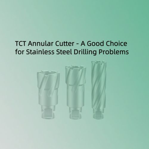
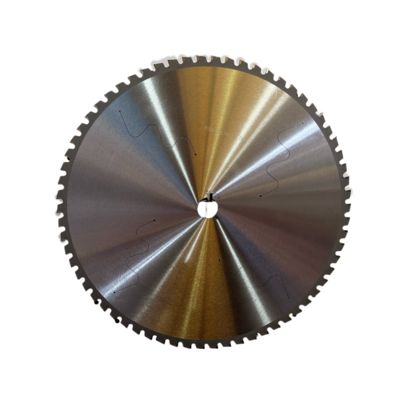
Annular Cutter: A Professional Tool to Overcome the Challenges of Drilling Stainless Steel
In the field of industrial machining, stainless steel has become a key material in manufacturing due to its excellent corrosion resistance, high strength, and good toughness. However, these same properties also pose significant challenges for drilling operations, making stainless steel drilling a demanding task. Our annular cutter, with its unique design and outstanding performance, provides an ideal solution for efficient and precise drilling in stainless steel.
Ⅰ. Challenges and Core Difficulties in Drilling Stainless Steel
1.High Hardness and Strong Wear Resistance:
Stainless steel, particularly austenitic grades like 304 and 316, has high hardness that significantly increases cutting resistance—over twice that of regular carbon steel. Standard drill bits dull quickly, with wear rates increasing by up to 300%.
2.Poor Thermal Conductivity and Heat Accumulation:
The thermal conductivity of stainless steel is only one-third that of carbon steel. The cutting heat generated during drilling cannot dissipate quickly, causing localized temperatures to exceed 800°C. Under such high-temperature and high-pressure conditions, alloy elements in stainless steel tend to bond with the drill material, leading to adhesion and diffusion wear. This results in drill bit annealing failure and workpiece surface hardening.
3.Significant Work Hardening Tendency:
Under cutting stress, some austenite transforms into high-hardness martensite. The hardness of the hardened layer can increase by 1.4 to 2.2 times compared to the base material, with tensile strength reaching up to 1470–1960 MPa. As a result, the drill bit is constantly cutting into increasingly harder material.
4.Chip Adhesion and Poor Chip Evacuation:
Due to the high ductility and toughness of stainless steel, chips tend to form continuous ribbons that easily adhere to the cutting edge, forming built-up edges. This reduces cutting efficiency, scratches the hole wall, and leads to excessive surface roughness (Ra > 6.3 μm).
5.Thin Plate Deformation and Positioning Deviation:
When drilling sheets thinner than 3mm, the axial pressure from traditional drill bits can cause material warping. As the drill tip breaks through, unbalanced radial forces may lead to poor hole roundness (commonly deviating by more than 0.2mm).
These challenges make conventional drilling techniques inefficient for stainless steel processing, calling for more advanced drilling solutions to effectively address these issues.
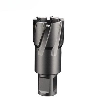
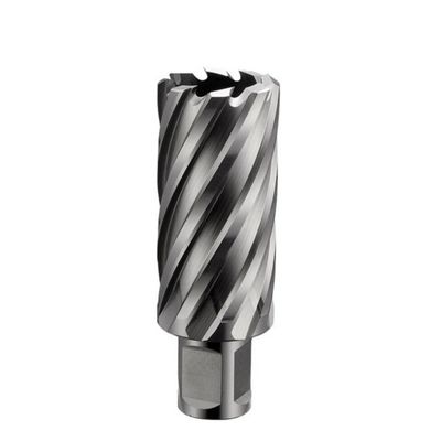
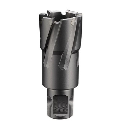
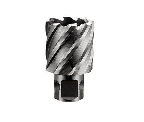
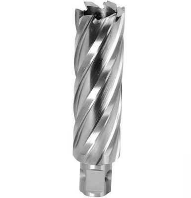
Ⅱ. Definition of Annular Cutter
An annular cutter, also known as a hollow drill, is a specialized tool designed for drilling holes in hard metal plates such as stainless steel and thick steel sheets. By adopting the principle of annular (ring-shaped) cutting, it overcomes the limitations of traditional drilling methods.
The most distinctive feature of the annular cutter is its hollow, ring-shaped cutting head, which removes only the material along the hole's perimeter rather than the entire core, as with conventional twist drills. This design dramatically enhances its performance, making it far superior to standard drill bits when working with thick steel plates and stainless steel.
Ⅲ. Core Technical Design of the Annular Cutter
1.Three-Edge Coordinated Cutting Structure:
The composite cutting head consists of outer, middle, and inner cutting edges:
Outer Edge: Cuts a circular groove to ensure precise hole diameter (±0.1mm).
Middle Edge: Bears 60% of the main cutting load and features wear-resistant carbide for durability.
Inner Edge: Breaks the material core and aids in chip removal. The uneven tooth pitch design helps prevent vibration during drilling.
2.Annular Cutting & Chip-Breaking Groove Design:
Only 12%–30% of the material is removed in a ring shape (core retained), reducing cutting area by 70% and lowering energy consumption by 60%. Specially engineered spiral chip grooves automatically break chips into small fragments, effectively preventing ribbon-shaped chip entanglement—a common issue when drilling stainless steel.
3.Central Cooling Channel:
Emulsion coolant (oil-to-water ratio 1:5) is directly sprayed to the cutting edge through a central channel, reducing the temperature in the cutting zone by over 300°C.
4.Positioning Mechanism:
The center pilot pin is made of high-strength steel to ensure accurate positioning and prevent drill slippage during operation—especially important when drilling slippery materials like stainless steel.
Ⅳ. Advantages of Annular Cutters in Drilling Stainless Steel
Compared to traditional twist drills that perform full-area cutting, annular cutters remove only a ring-shaped section of the material—retaining the core—which brings revolutionary advantages:
1.Breakthrough Efficiency Improvement:
With a 70% reduction in cutting area, drilling a Φ30mm hole in 12mm-thick 304 stainless steel takes just 15 seconds—8 to 10 times faster than using a twist drill. For the same hole diameter, annular cutting reduces workload by over 50%. For example, drilling through a 20mm-thick steel plate takes 3 minutes with a traditional drill, but only 40 seconds with an annular cutter.
2.Significant Reduction in Cutting Temperature:
Central cooling fluid is directly injected into the high-temperature zone (optimal ratio: oil-water emulsion 1:5). Combined with layered cutting design, this keeps the cutter head temperature below 300°C, preventing annealing and thermal failure.
3.Guaranteed Precision and Quality:
Multi-edge synchronized cutting ensures automatic centering, resulting in smooth, burr-free hole walls. Hole diameter deviation is less than 0.1mm, and surface roughness is Ra ≤ 3.2μm—eliminating the need for secondary processing.
4.Extended Tool Life and Reduced Costs:
The carbide cutting head withstands the high abrasiveness of stainless steel. Over 1,000 holes can be drilled per regrind cycle, reducing tool costs by up to 60%.
5.Case Study:
A locomotive manufacturer used annular cutters to drill 18mm holes in 3mm-thick 1Cr18Ni9Ti stainless steel base plates. The hole pass rate improved from 95% to 99.8%, roundness deviation decreased from 0.22mm to 0.05mm, and labor costs were reduced by 70%.
Ⅴ. Five Core Challenges and Targeted Solutions for Drilling Stainless Steel
1.Thin-Wall Deformation
1.1Problem: Axial pressure from traditional drill bits causes plastic deformation of thin plates; at breakthrough, radial force imbalance leads to oval-shaped holes.
1.2.Solutions:
Backing Support Method: Place aluminum or engineering plastic backing plates under the workpiece to distribute compressive stress. Tested on 2mm stainless steel, ovality deviation ≤ 0.05mm, deformation rate reduced by 90%.
Step Feed Parameters: Initial feed ≤ 0.08 mm/rev, increase to 0.12 mm/rev at 5mm before breakthrough, and to 0.18 mm/rev at 2mm before breakthrough to avoid critical speed resonance.
2. Cutting Adhesion and Built-Up Edge Suppression
2.1.Root Cause: Welding of stainless steel chips to the cutting edge at high temperature (>550°C) causes Cr element precipitation and adhesion.
2.2.Solutions:
Chamfered Cutting Edge Technology: Add a 45° chamfer edge 0.3-0.4mm wide with 7° relief angle, reducing blade-chip contact area by 60%.
Chip-Breaking Coating Application: Use TiAlN coated drill bits (friction coefficient 0.3) to reduce built-up edge rate by 80% and double tool life.
Pulsed Internal Cooling: Lift drill every 3 seconds for 0.5 seconds to allow cutting fluid penetration at adhesion interface. Combined with 10% extreme pressure emulsion containing sulfur additives, temperature in cutting zone can drop by over 300°C, significantly reducing welding risk.
3. Chip Evacuation Issues and Drill Jamming
3.1.Failure Mechanism: Long strip chips entangle the tool body, blocking coolant flow and eventually clogging the chip flutes, causing drill breakage.
3.2.Efficient Chip Evacuation Solutions:
Optimized Chip Flute Design: Four spiral flutes with 35° helix angle, increased flute depth by 20%, ensuring each cutting edge chip width ≤ 2mm; reduces cutting resonance and cooperates with spring push rods for automatic chip clearing.
Air Pressure Assisted Chip Removal: Attach 0.5MPa air gun on magnetic drill to blow away chips after each hole, reducing jamming rate by 95%.
Intermittent Drill Retraction Procedure: Fully retract drill to clear chips after reaching 5mm depth, especially recommended for workpieces thicker than 25mm.
4. Curved Surface Positioning and Perpendicularity Assurance
4.1.Special Scenario Challenge: Drill slipping on curved surfaces like steel pipes, initial positioning error >1mm.
4.2.Engineering Solutions:
Cross Laser Positioning Device: Integrated laser projector on magnetic drill projects crosshair on curved surface with ±0.1mm accuracy.
Curved Surface Adaptive Fixture: V-groove clamp with hydraulic locking (clamping force ≥5kN) ensures drill axis parallel to surface normal.
Stepwise Starting Drill Method: Pre-punch 3mm pilot hole on curved surface → Ø10mm pilot expansion → target diameter annular cutter. This three-step method achieves verticality of Ø50mm holes at 0.05mm/m.
Ⅵ.Stainless Steel Drilling Parameter Configuration and Cooling Fluid Science
6.1 Golden Matrix of Cutting Parameters
Dynamic adjustment of parameters according to stainless steel thickness and hole diameter is the key to success:
Workpiece Thickness
Hole Diameter Range
Spindle Speed (r/min)
Feed Rate (mm/rev)
Coolant Pressure (bar)
1-3 mm
Ø12-30 mm
450-600
0.10-0.15
3-5
3-10 mm
Ø30-60 mm
300-400
0.12-0.18
5-8
10-25 mm
Ø60-100 mm
150-250
0.15-0.20
8-12
>25 mm
Ø100-150 mm
80-120
0.18-0.25
12-15
Data compiled from austenitic stainless steel machining experiments.
Note: Feed rate < 0.08 mm/rev aggravates work hardening; > 0.25 mm/rev causes insert chipping. Strict matching of speed and feed ratio is necessary.
6.2 Coolant Selection and Usage Guidelines
6.2.1.Preferred Formulations:
Thin Plates: Water-soluble emulsion (oil:water = 1:5) with 5% sulfurized extreme pressure additives.
Thick Plates: High-viscosity cutting oil (ISO VG68) with chlorine additives to enhance lubrication.
6.2.2.Application Specifications:
Internal Cooling Priority: Coolant delivered through drill rod center hole to the drill tip, flow rate ≥ 15 L/min.
External Cooling Assistance: Nozzles spray coolant onto chip flutes at a 30° inclination.
Temperature Monitoring: Replace coolant or adjust formulation when cutting zone temperature exceeds 120°C.
6.3 Six-Step Operation Process
Workpiece clamping → Hydraulic fixture locking
Center positioning → Laser cross calibration
Drill assembly → Check insert tightening torque
Parameter setting → Configure according to thickness-hole diameter matrix
Coolant activation → Pre-inject coolant for 30 seconds
Stepwise drilling → Retract every 5mm to clear chips and clean flutes
Ⅶ. Selection Recommendations and Scenario Adaptation
7.1 Drill Bit Selection
7.1.1.Material Options
Economical Type: Cobalt High-Speed Steel (M35)
Applicable scenarios: 304 stainless steel thin plates 2000 holes, TiAlN coating friction coefficient 0.3, reduces built-up edge by 80%, solves adhesion issues with 316L stainless steel.
Special Reinforced Solution (Extreme Conditions): Tungsten Carbide substrate + Nanotube coating
Nanoparticle reinforcement improves bending strength, heat resistance up to 1200°C, suitable for deep hole drilling (>25mm) or stainless steel with impurities.
7.1.2.Shank Compatibility
Domestic Magnetic Drills: Right-angle shank.
Imported Magnetic Drills (FEIN, Metabo): Universal shank, quick-change system supported, runout tolerance ≤ 0.01mm.
Japanese Magnetic Drills (Nitto): Universal shank only, right-angle shanks not compatible; require dedicated quick-change interface.
Machining Centers / Drilling Machines: HSK63 hydraulic tool holder (runout ≤ 0.01mm).
Handheld Drills / Portable Equipment: Four-hole quick-change shank with self-locking steel balls.
Special Adaptation: Conventional drill presses require Morse taper adapters (MT2/MT4) or BT40 adapters for compatibility with annular cutters.
7.2 Typical Scenario Solutions
7.2.1.Steel Structure Thin Plate Connection Holes
Pain Point: 3mm thick 304 stainless steel thin plates prone to deformation; roundness deviation > 0.2mm.
Solution:Drill bit: HSS right-angle shank (cutting depth 35mm) + magnetic drill with adsorption force > 23kN.
Parameters: Speed 450 rpm, feed 0.08 mm/rev, coolant: oil-water emulsion.
7.2.2.Shipbuilding Thick Plate Deep Hole Machining
Pain Point: 30mm thick 316L steel plates, traditional drill takes 20 minutes per hole.
Solution:
Drill bit: TiAlN coated carbide drill (cutting depth 100mm) + high-pressure cutting oil (ISO VG68).
Parameters: Speed 150 rpm, feed 0.20 mm/rev, stepwise chip evacuation.
7.2.3.Rail High Hardness Surface Hole Drilling
Pain Point: Surface hardness HRC 45–50, prone to edge chipping.
Solution:
Drill bit: Tungsten carbide four-hole shank drill + internal cooling channel (pressure ≥ 12 bar).
Assistance: V-type fixture clamping + laser positioning (±0.1mm accuracy).
7.2.4.Curved/Inclined Surface Positioning
Pain Point: Slippage on curved surface causes positioning error > 1mm.
Solution:Three-step drilling method: Ø3mm pilot hole → Ø10mm expansion hole → target diameter drill bit. Equipment: Magnetic drill integrated with cross laser positioning.
Ⅷ.Technical Value and Economic Benefits of Steel Plate Drilling
The core challenge of stainless steel drilling lies in the conflict between the material’s properties and traditional tooling. The annular cutter achieves a fundamental breakthrough through three major innovations:
Annular cutting revolution: removes only 12% of the material instead of full cross-section cutting.
Multi-edge mechanical load distribution: reduces load per cutting edge by 65%.
Dynamic cooling design: lowers cutting temperature by more than 300°C.
In practical industrial validations, annular cutters deliver significant benefits:
Efficiency: Single hole drilling time is reduced to 1/10 of that with twist drills, increasing daily output by 400%.
Cost: Insert life exceeds 2000 holes, reducing overall machining cost by 60%.
Quality: Hole diameter tolerance consistently meets IT9 grade, with near-zero scrap rates.
With the popularization of magnetic drills and advancements in carbide technology, annular cutters have become the irreplaceable solution for stainless steel processing. With correct selection and standardized operation, even extreme conditions such as deep holes, thin walls, and curved surfaces can achieve highly efficient and precise machining.
It is recommended that enterprises build a drilling parameter database based on their product structure to continuously optimize the entire tool lifecycle management.